|
|
|
|
READ AND SAVE THESE INSTRUCTIONS
|
|
INSTALLATION, OPERATING INSTRUCTIONS & PARTS MANUAL
|
|
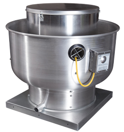
Centrifugal Upblast Exhaust Fan
|
|
Direct Drive for Roof & Wall Mounting
|
|
|
Electrical wiring and connections should be done in accordance with local
ordnances and the National Electric Code, NFPA70. Be sure the voltage and
phase of the power supply and the wire amperage capacity is in accordance
with the motor nameplate. For additional safety information refer to AMCA
publication 410-96, Recommended Safety Practices for Users and Installers
of Industrial and Commercial Fans.
|
|
Upon receiving unit, check for any damage and report it immediately to the
carrier. Also check that all accessory items are accounted for.
|
|
|
|
|
Installation of this ventilator should only be performed by a
qualified professional who has read and understands these instructions
and is familiar with proper safety precautions. Improper installation
poses serious risk of injury due to electric shock, contact with rotating
equipment and other potential hazards. Special considerations resulting from
high winds or seismic activity may be required. Consult with a licensed
professional engineer for more information if necessary.
|
- Wheel must be free to rotate and should not strike or rub any
stationary object.
- Follow all local electrical and safety codes, as well as the
National Electrical Code (NEC), the Occupational Safety and
Health Act (OSHA), and the National Fire Protection Association
(NFPA) Bulletin 96, where applicable.
- Motor must be securely and adequately grounded.
- Always disconnect power before working on or near a fan. Lock and
tag the disconnect switch or breaker to prevent accidental power up.
- Caution-when servicing fan, motors may be hot enough to cause pain
or injury. Allow motor to cool before servicing.
- Secure the power cable to prevent contact with sharp objects.
- Do not kink power cable and never allow the cable to come in contact
with oil, grease, hot surfaces or chemicals.
- Make certain that the power source is compatible with the
requirements of your equipment.
- Wiping or cleaning rags and other flammable waste materials
must be placed in a tightly closed container and disposed of later
in a proper fashion.
|
|
|
WARNING: DISCONNECT POWER BEFORE INSTALLING OR SERVICING.
|
|
Caution: Do not raise ventilator by its windband, wheel,
or motor– use a sling or platform
|
|
- Ventilators are designed for installation atop a prefabricated or
factory built roof curb. Follow manufacturer’s instructions for
proper curb installation.
- If a backdraft damper is required, it should be secured within the
curb using sheet metal screws, to the bottom of a damper box or
damper support flanges located below the roof deck. CAUTION:
NFPA-96 RECOMMENDS THAT DAMPERS SHOULD NOT BE INSTALLED WHEN EXHAUSTER
IS USED FOR REMOVAL OF SMOKE AND GREASE LADEN VAPORS FROM COMMERCIAL
KITCHEN EQUIPMENT. CONSULT STATE AND LOCAL CODES FOR DETAILED
REQUIREMENTS.
- If fan is used for kitchen hood exhaust ensure discharge is at
least 40 inches above the roof surface in accordance with NFPA96.
- Normally the power cord is brought through the conduit tube located
on the top skirt on the outside of the unit.
- Secure ventilator curb through vertical portion of the ventilator
base assembly flange using a minimum of eight (8) lug screws, anchor
bolts, or other suitable fasteners (not furnished).
- Before connecting fan motor to power source verify power line wiring
is de-energized.
- Connect power supply wiring to the motor as indicated on the
motor nameplate or terminal box cover. Make certain that the power
source is compatible with the requirements of your equipment.
- Before powering up fan check ventilator wheel for free rotation.
- Check all fasteners for tightness.
- Re-install motor dome.
- A drain pipe is provided for single-point drainage of water and residue.
The drain pipe should be positioned towards the roof slope. Some means for
collection of this residue must be provided, either a container directly
under the trough or use of an adapter and pipe to carry the residue to a
remote collection point.
An optional down spout and grease collection box is available as an accessory
item for this unit.
|
|
- The same instructions, warnings and notes found under Roof Mounting
section will apply. Refer to steps 2 and 3, and steps 5 through 8.
- Masonry Wall:
| Around the wall opening install an angle iron frame at least
2” x 2" x 1/8”. Frame should be approximately 1/2" smaller than
the inside base dimension of the ventilator. Secure the lead
cinch type anchors with non-ferrous bolts (3 per side).
The ventilator should be mounted to the mounting angle with
self-taping sheet metal screws (3 per side). |
- Wood Sidings:
| Around the wall opening install a wooden frame 2” high x 2” wide.
Frame should be approximately 1/2" smaller than the inside base
dimension of the ventilator. Secure with counter-sunk
expansion type lag bolts (3 per side). The ventilator should
then be mounted to the mounting frame with the square head wood
screws (3 per side) 3/8” minimum. |
NOTE: If factory supplied hinge kit is used make wall mounting
frame 1-1/2” smaller that fan base dimension to accommodate hinge assembly.
- The mounting flange connections should be coated with a suitable
caulking compound or an approved waterproof mastic sealer.
- Wall mount application is not recommended from fans 30” or larger.
IMPORTANT: OSHA REGULATIONS REQUIRE THE VENTILATOR TO BE MOUNTED
AT LEAST EIGHT (8) FEET ABOVE GROUND OR FLOOR LEVEL.
|
|
|
- Before starting up or operating the ventilator, check all fasteners
for tightness. In particular, check the set screw in the wheel hub.
With power to the fan OFF or prior to connecting ventilator to power,
turn the fan wheel by hand to be sure it is not striking the inlet or
any obstacles.
- Start the fan up and shut it off immediately to check rotation of the
wheel with the directional arrow in the motor compartment. Fan wheel
should rotate counter-clockwise when viewed
from the top. Reversed
rotation will result in poor air performance, motor overloading and
possible burnout. For units equipped with a single-phase motor check
the motor wiring diagram to change rotation.
- When the fan is started up, observe the operation and check for any
unusual noises.
- With the air system in full operation and all ducts attached, measure
the current input to the motor and compare with the motor nameplate to
determine if the motor is operating under safe load condition.
- Keep inlets and approaches to the ventilator clean and free from
obstruction.
- To adjust the fan speed, adjust the rheostat. To increase the fan speed,
turn the rheostat counter- clockwise. To reduce the fan speed,
turn the rheostat clockwise.
|
|
|
WARNING: DO NOT ATTEMPT MAINTENANCE ON THE FAN UNTIL THE ELECTRICAL SUPPLY
HAS BEEN COMPLETELY DISCONNECTED.
|
- Fan inlet and approaches to ventilator should be kept clean and free
from any obstruction.
- Motors are permanently lubricated, no further lubrication is necessary.
Caution: Use care when touching the exterior of an operating motor.
Motors normally run hot and may be hot enough to be painful or cause injury.
- To remove motor or Impeller:
- Remove motor hood, cooling tube, and electric wire from switch
or junction box.
- Remove the fastening bolts and nuts that secure the top plate to
the supporting braces and remove the entire assembly from the housing.
- Loosen setscrew(s) on wheel hub to slip fan impeller from shaft.
- To remove motor, remove retaining bolts and nuts on motor mounting plate.
- Wheels require very little attention when moving clean air. Occasionally oil
and dust may accumulate causing imbalance. If the fan is installed in a
corrosive or dirty atmosphere, periodically inspect and clean the wheel,
inlet and other moving parts to ensure smooth and safe operation.
- All fasteners should be checked for tightness each time maintenance
checks are preformed prior to restarting unit.
|
|
|
Problems and Potential Cause
|
|
- Open circuit breaker or overload in starter set too low.
Reset circuit breaker or check setting of overload.
- Motor wired incorrectly. Check motor wiring to wiring
diagram located on fan motor.
|
- Fan rotating in the wrong direction. Be sure fan is
rotating counter-clockwise looking down on wheel.
- Poor inlet conditions. There should be a straight clear
duct at the inlet.
- Be sure duct access doors are closed and dampers are
operating properly.
|
- Fan rotating in the wrong direction. Be sure fan
is rotating counter-clockwise looking down on wheel.
- Worn motor bearings. Replace or repair motor.
- Damaged or unbalanced wheel.
- Fan is operating in the unstable region of the fan curve.
|
- Fan rotating in the wrong direction. Be sure fan is
rotating counter-clockwise looking down on wheel.
- Motor wired incorrectly. Check motor wiring to wiring
diagram located on fan motor.
- Overload in starter set too low.
| |
|
|
|
Warranty
This equipment is warranted to be free from defects in materials and workmanship, under normal use and
service, for a period of 24 months from date of shipment. This warranty shall not apply if:
- The equipment is not installed by a qualified installer per the MANUFACTURER'S installation
instructions shipped with the product,
- The equipment is not installed in accordance with federal, state and local codes and regulations,
- The equipment is misused or neglected,
- The equipment is not operated within its published capacity,
- The invoice is not paid within the terms of the sales agreement.
The MANUFACTURER shall not be liable for incidental and consequential losses and damages
potentially attributable to malfunctioning equipment. Should any part of the equipment prove to be
defective in material or workmanship within the 24-month warranty period, upon examination by the
MANUFACTURER, such part will be repaired or replaced by MANUFACTURER at no charge. The
BUYER shall pay all labor costs incurred in connection with such repair or replacement. Equipment shall
not be returned without MANUFACTURER'S prior authorization and all returned equipment shall be
shipped by the BUYER, freight prepaid to a destination determined by the MANUFACTURER.
|
|
|
|