
This site is protected by reCAPTCHA and the Google Privacy Policy and Terms of Service apply.
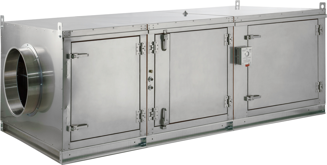
PCU
Pollution Control Unit
Pollution Under Control
System Description
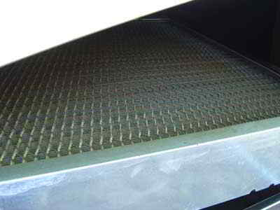
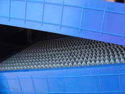
The typical PCU includes a washable steel pre-filter and disposable, high efficiency (MERV 15) media filter. An additional high efficiency (MERV 15) / HEPA module is available for smoke control. Odor control is handled via an optional module ( typically 50/50 blend carbon/permanganate OR 100% carbon blend). An optional ESP module is available for electronic-type air cleaning. Sizes range in capacity up to 20,000 CFM.
The PCU is ETL listed and is suitable for indoor or outdoor installations.
Product Resources
- Center of Mass Calculator
- Component Details
- Exploded Parts Detail - Short Filter Module
- Exploded Parts Detail - Last Filter Module
- Filter Efficiency Chart
- Fire System Connections
- PCU Fire System Information
- Fire System Size
- Independent Filter Capture Efficiency Testing
- Independent Odor Breakthrough Testing
- NYC Certificate of Approval
- NYC Environmental Certifications
- ESP Single Pass Efficiency
- PCU Blower Manual
- PCU Filtration Manual
- PCU Series Spec Sheet
- Pressure Drops
- Submittal Drawings
- Written Specification
Field Photos
Approvals
Applicable Standards: The PCU Series has been certified by ITS. This certification mark indicates that the product has been tested to and has met the minimum requirements of a widely recognized (consensus) U.S. and Canadian products safety standard, that the manufacturing site has been audited, and that the applicant has agreed to a program of periodic factory follow-up inspections to verify continued performance.
Models PCU are ETL listed under file number 103624182COL-001 and complies with ULC-S647, UL-8782, UL-1978, ULC-S662, UL-867, and ULC-C22.2 No. 187 Standards.
Models KB10-INLINE through KB25-INLINE are ETL Listed under file numbers 103336443COL-001 and 102628244PRT-001 and comply with UL705 (electrical), and ULC-S645 Standards and CSA Std C22.2, No 113.

CaptiveAire Systems, Inc. certifies that KB models shown herein are ETL Listed under file numbers 3158877SAT-001 and comply with ULC-S645 Standards and CSA Std C22.2, No. 113

Models PCU are UL listed under project number 4787163176 and complies with UL1978, ULCS662 Standards.
Sustainable By Design
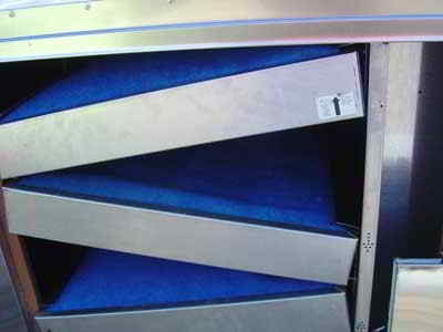
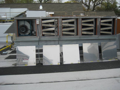
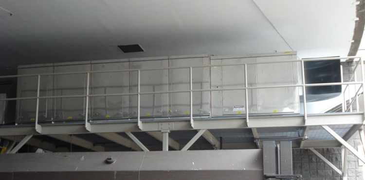
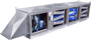
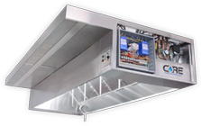
The CaptiveAire Pollution Control Unit, PCU Series, is designed specifically for the removal of grease particles and abatement of smoke from the air stream of commercial kitchen exhaust systems. The unit, if ordered with the optional odor control section, will reduce odors from the air stream. The PCU is designed for use with a CaptiveAire high efficiency self-cleaning or baffle ventilator but may be used with other high efficiency exhaust hoods.PCU (Inside View)

Features
- Constructed specifically to meet kitchen exhaust duct standards
- Optional Odor Removal Module
- Suitable for indoor or outdoor installation
- Unit may be shipped in one piece or in sections to facilitate entry and installation
- Optional Pre Filter Section
- Optional exhaust fan
- Optional Advanced Filter Monitoring System
- Optional CORE Protection Fire System
Benefits
- Pre-engineered for the most efficient and cost-effective systems
- Listed by ETL Testing Laboratories, assuring acceptance by local building officials
- Two year parts warranty
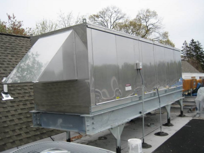
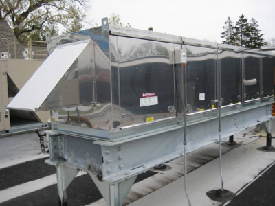
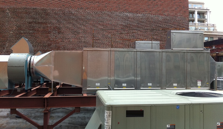
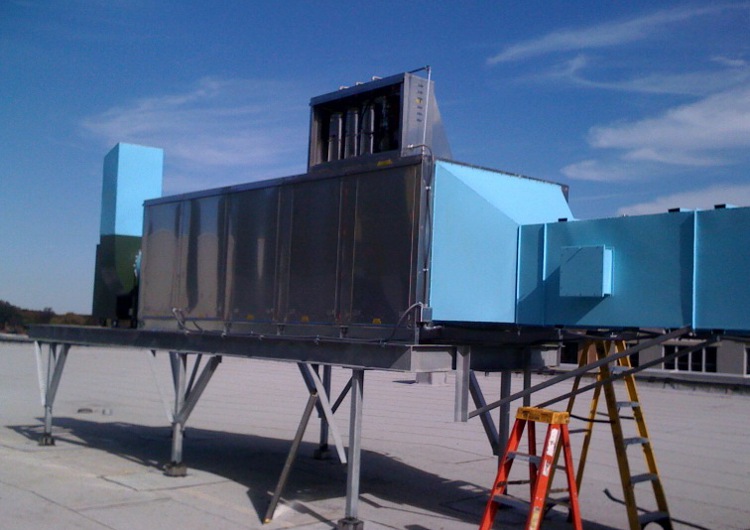
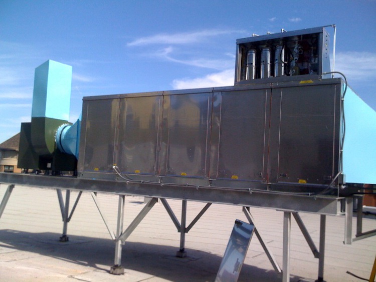
PCU with optional exhaust fan
Fan Features & Benefits
- TEFC, Class H insulation, washdown duty motors
- Heavy duty construction, durable and weather resistant
- Non-overloading backward inclined wheels
- Quick release latches allow for easy access to motor compartment
- High efficiency combined with low tip speeds results in quiet operation
- Standard emergency disconnect switch
Fan Options
- Opposite Side Controls
- Roof Equipment Rails
- Side Discharge Outdoor Screen
System Description
The Advanced Filter Monitoring includes a module that provides the necessary precision pressure measurements for accurate monitoring of the complete system. Based on the measurements, the module will then initiate actions via the electric control package and give readings to the user. Direct access to the operating conditions are provided through the use of an HMI (human machine interface), which is conveniently located on the PCU.
System Features
Monitors Pressure Drop across each filter module of the PCU
Missing Door or Missing Filter Indication - fans and cooking equipment will shut off if faults indicated.
Detects Filter Saturation Percentage
Advanced Filter Monitoring System
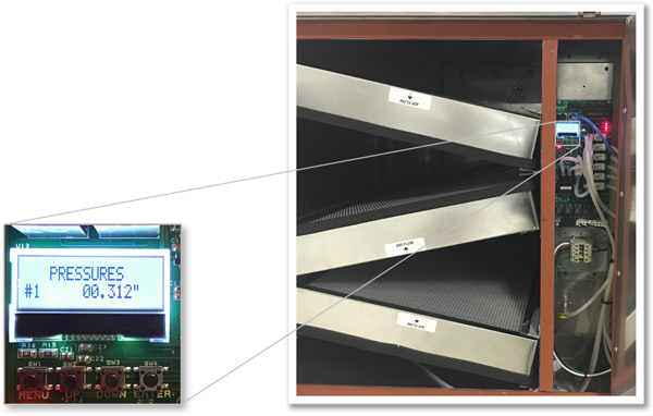 The Pollution Control Unit (PCU) with Advanced Filter Monitoring option offers an automated assessment of the unit to ensure proper operation.
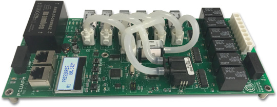 HMI - human machine interface

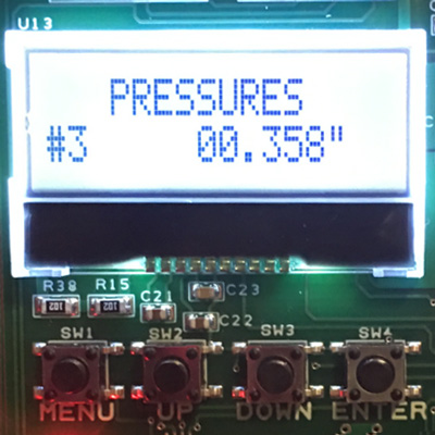 Screen showing Pressure Drop across Modules
 Monitor Pressure Drop across each filter module
Advanced Filter Monitoring Benefits
- Sustainability – Sustainability - Extends life of various filters, addresses specific filters which need replacement based on monitoring
- Ease of Installation and Startup – automatic calibration of the system via HMI
- Maintenance – Provides advanced notice, pinpoints specific faults to address
- Reliability – Ensures proper operation of the PCU
Related Product
The SCS Control Panel is ideal for ESP self-cleaning system

Click here to view this product »
Electrostatic Precipitator (ESP)
")
Overview
An electrostatic precipitator (ESP) is an electronic air cleaner used to mitigate smoke and grease from commercial kitchen exhaust air streams. An ESP cell module can be integrated with other PCU filter modules. The ESP cell module has an integrated self-cleaning system to reduce maintenance costs.
Benefits
- Complete Solution – Interlocked with fans, self-cleaning system, and fire system controls
- Reduces Maintenance – Self-cleaning system for ESP cells
- Lower Pressure Drop – Lower pressure drop than comparable mechanical filters
- Engineered to Your Needs – Flexible filter and ESP module configurations
- Superior Durability – Spiked rigid plate ionizer and ceramic isolators ensure superior durability; more robust than wire-type ionizers
Options
- Pre and Post-Filters – Captrate© Solo and mesh filters keep water contained in the ESP module during a self-cleaning cycle and protect ESP cells from foreign debris
- PCU CORE – For a reliable Fire Protection System
- SCS Control Panel – Ideal for ESP self-cleaning system
How ESPs Work
Grease and smoke-laden exhaust pass through the ionizer section of the ESP cell(s). The cell design uses a spiked rigid plate to ionize the air stream through the phenomenon known as corona.
The charged air stream then flows through the collector section where particles are collected.

 The above image shows the blue corona which is visible to the naked eye in low-light conditions.

System Description
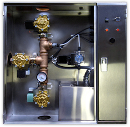
The detection portion of the fire suppression system allows for automatic detection by means of an electric thermal detector located in the intake and outlet of the ductwork connection. If the Pollution Control Unit Firestat senses a temperature hotter than its internal setpoint, an electric signal is sent to the CORE Fire System Cabinet. An electric water solenoid is energized allowing the flow of water to the Pollution Control Unit mounted manifold.
The CORE fire suppression system is a pre-engineered, pollution control unit fire system that utilizes a water spray system for fast flame knock-down and suppression.
A system owner's guide is available containing basic information pertaining to system operation and maintenance. The system is installed and serviced by authorized distributors that are trained by the manufacturer.
The CORE circuit board is an ETL Recognized Component under Report number 101196419NYM-001. The PCBCORE board is certified as a releasing service for the CORE Protection Fire System.
Product Resources
- Duct Sensor Installation Diagram
- Duct Sensor Installation Diagram
- Interlock Connection
- Interlock Connection for Hood Mounted CORE
- Electrically Reversible Interlock Connection for Hood Mechanical Fire System
- Installation Summary
- Submittal Drawings
- Written Specification
- CORE Protection Manual
- Thermal Sensor Installation Instructions
Related Product
CORE Fire Protection for Commercial Kitchens
Click here to view this product »
PCU - Fire Suppression Systems
PCU CORE Control Panel
Application
The system is ideally suited for use in restaurants, hospitals, nursing homes, hotels, schools, airports, and other similar facilities.
The PCU CORE control panel is limited to interior applications only. The system must be designed and installed within the guidelines of the Listed Design, Installation, Recharge, and Maintenance Manual.
Features
- Electric Fire Detection with Battery Backup System
- Electric Remote Pull Station
- Factory Installed in Utility Cabinet
Benefits
- System Reliability
- Microprocessor Based Control to ensure Reliable Operation
- Easy Installation and Service
- Fire Suppression sprays until risk of fire is eliminated
Component Descriptions
Overview of all the pieces and parts that make up the CORE Fire Protection System.
CORE Circuit Board
The CORE Fire System printed circuit board is a microprocessor based control that provides all the necessary monitoring, timing and supervision functions required for the reliable operation of the CORE Protection Fire System. If a fault is detected anywhere in the CORE system, the audible alarm will periodically sound and the "Fire System Activated" light will flash a fault code to indicate the specific fault detected.
Electric System with Battery Backup
The detection and pull station for CORE comprise an electric circuit that is connected to a battery backup system. In the event of a power outage, the power to all gas and electric appliances must be disrupted through the use of electric gas valves or shunt trip breakers. The battery powers the detection and pull station circuits, as well as monitoring those devices.
Supervised Loop
The supervised loop incorporates both redundancy and fault detection. It is the means by which fire sensors and pull stations are connected to the CORE system.
CORE Control Cabinet
The CORE Control Cabinet contains most of the necessary components for the fire system to function. The control cabinet holds the manifold, surfactant tank and pump, CORE control board, power supply and battery backup.